Kawai SX-210 Enhanced Modification
Back in approx. 2004 I have received a non working Kawai SX-210 as a gift from a friend. After checking all the supply voltages I have realized it will not be so easy to fix it. I have removed the battery as it has not leaked yet. So due to other priorities I have stored the synth for 13 years in a corner of my studio. 2017 I wanted to hear how it sounds like. Furthermore I killed one key of the keyboard while carrying it through a door - common issue... So I started to fix the synth. After hours with a scope I have figured out the main issues of the synth:
- broken CPU
- several logic ICs were dead
- some traces on the PCB were interrupted
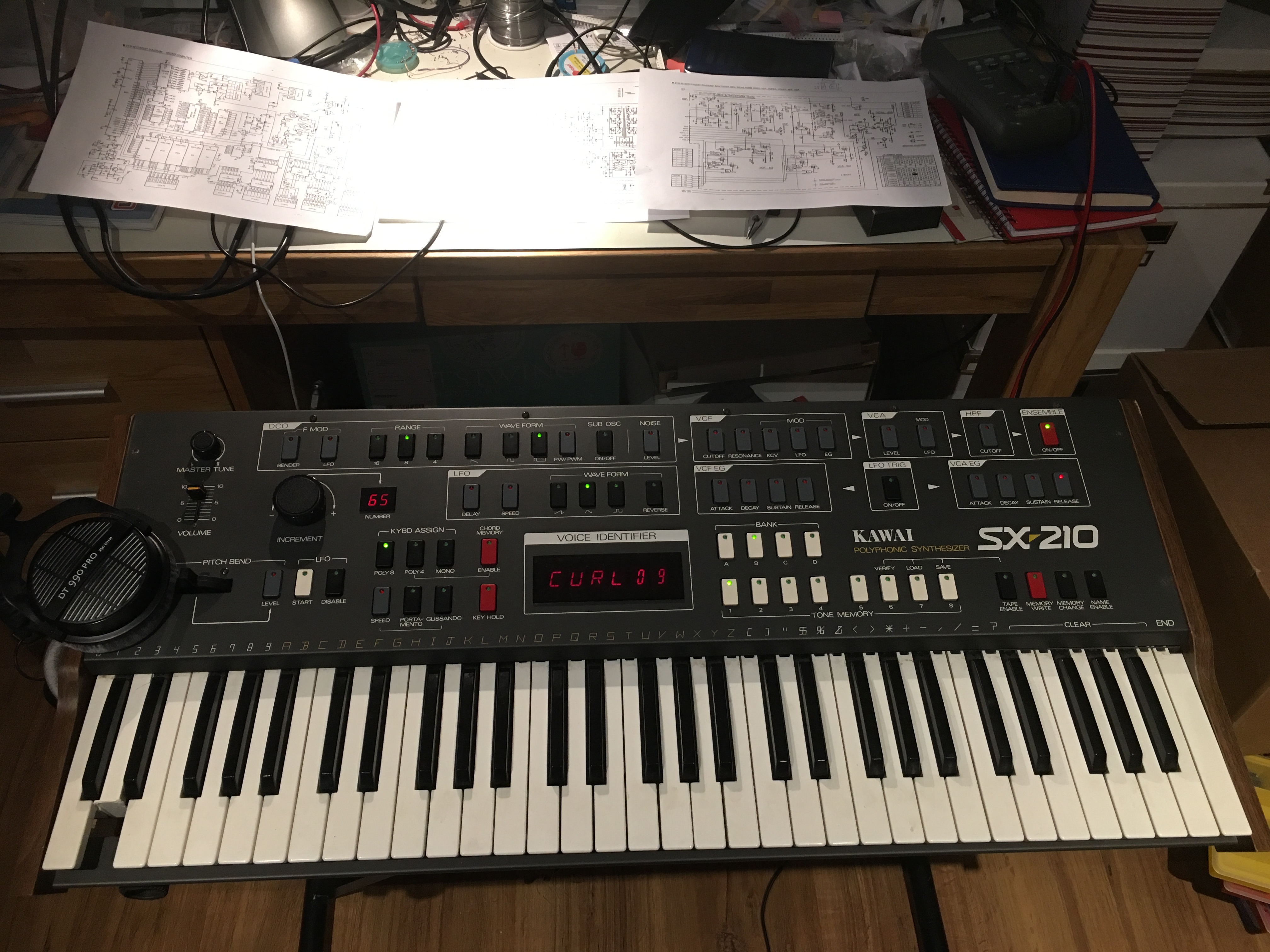
After fixing them and soldering sockets for the ICs on the PCB the synth was starting up the first time:
Just a small warning: the used PCB material of the SX-210 is realy fragile. I have not seen something simular before in my whole life. I would call myself not a novice, but I would really refer to an expert in case of any soldering work in this case! Touching the PCB with a soldering iron is most likely damaging the printed pins and traces on the PCB even with low soldering temperatures! For that reason I had to fix a lot of traces by wires afterwards.
The next I have noticed was that several voices were dead or had issues with the envelopes. In this case it is wise to have a closer look on the CD4066 chips in the EG sections on the voice board. In the end I had to replace 4 of them. Now all voices were playing fine. And again I had to replace some traces by wires.
As the SX-210 does not have any MIDI I started to develop a small MIDI interface based on a Microchip dsPI30F MCU. As I wanted to control the cutoff via MIDI I added also a DAC in order to generate a control voltage for the filters. Attaching 8 wires to all voices I was able to control cutoff by MIDI, but on all 8 voices simultaneously. Better than nothing...
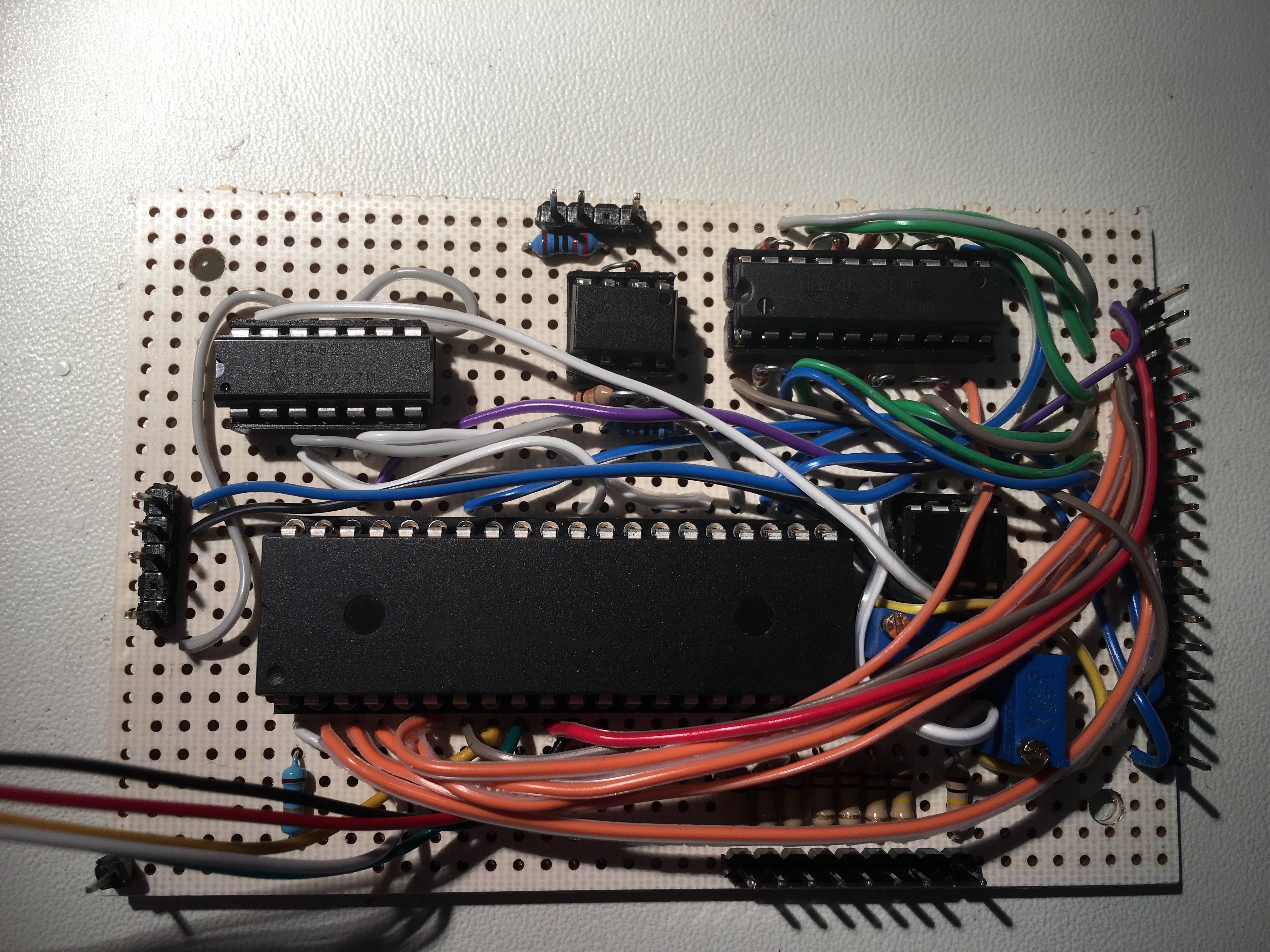
The interface
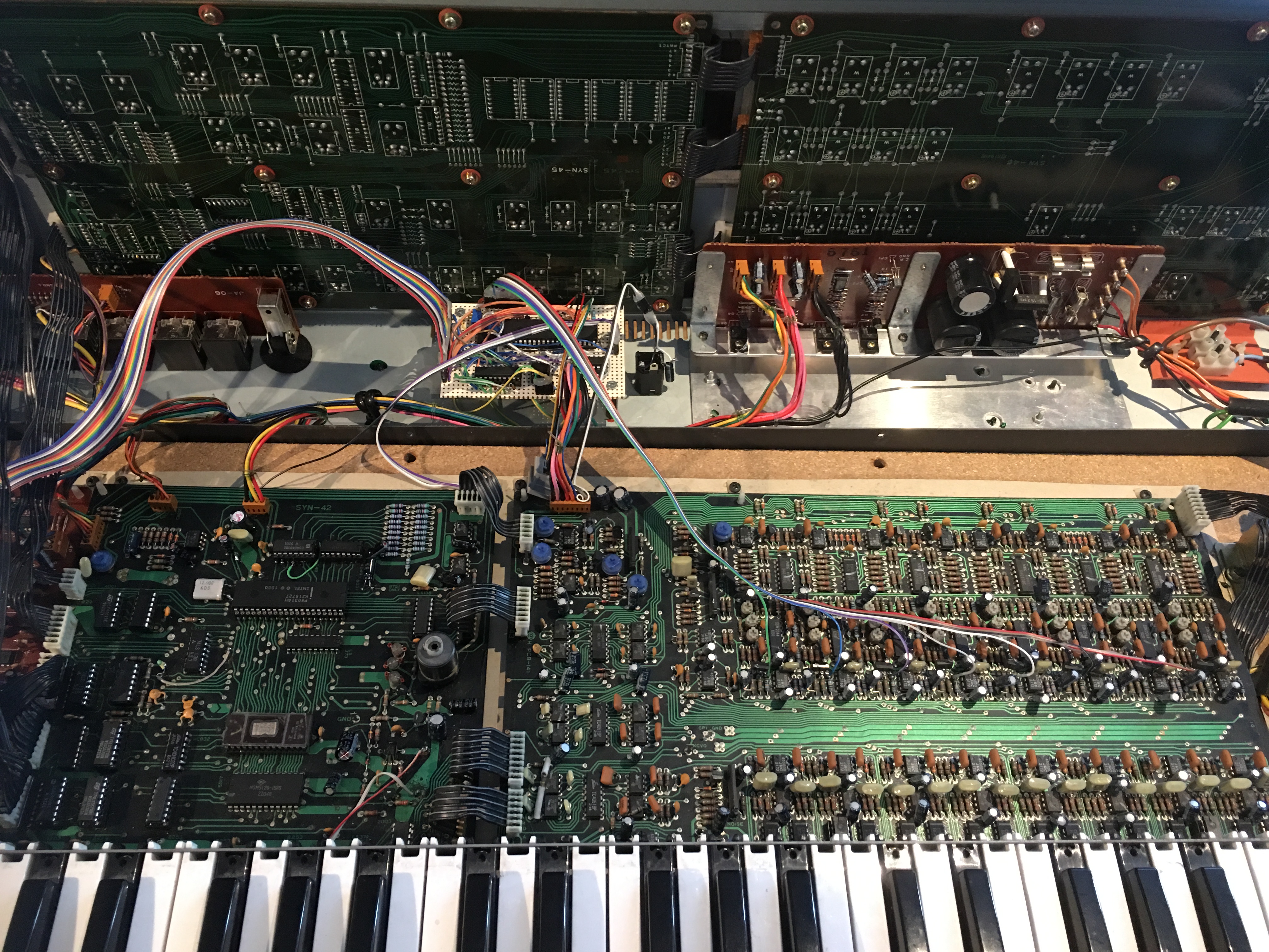
The interface installed
After a friend visited me I wanted to show him the interiour of the SX-210 and lifted up the front panel to have a look. Afterwards the synth was dead again. No! So I checked the chip select lines of the computer board and found a dead trace in a short term of time. After fixing it the synth was up and running again. I played with it in the next 2 weeks and went on holiday for one week. After returning I powered up the synth again - and you guess - not working anymore! Doh!
Now things became not so easy to fix anymore. I was not able to find the root cause as all data and address lines were working. Chip select lines were also toggling, but the synth was not starting up anymore. I have reprogrammed the EPROM - also no improvement. Damn! After spending about 200 hours to find the root case I finally gave up! The computer PCB meanwhile looked like this on the bottom:
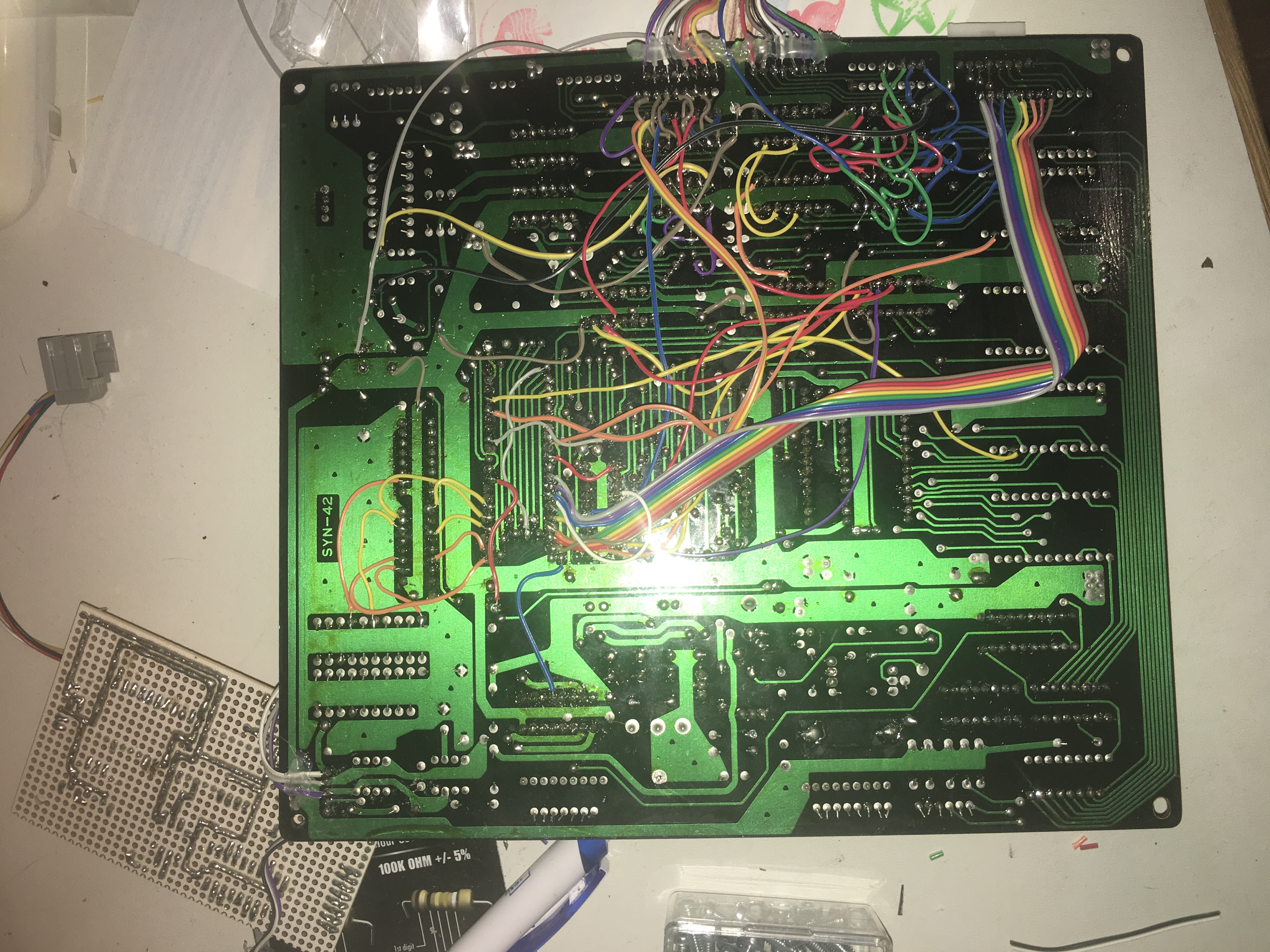
Original SYN42 PCB with all reworked traces...
Now decision time started with two options:
a) dump the unit as it is in frustration
b) sell it on eBay as it is
c) let some time pass by and do something else
Due to the fact I was working on some own synthesizers I have choosen to follow up option c.
Another year has passed and I remembered this little fella still catching dust in the corner of my studio. My thoughts were shall I spend another 200 hours of useless time in order to *try* to fix it, or shall I follow a completly new route.
So my decision was to dump the old computer PCB and start developing a new one. After starting a PCB software I started to repaint the schematics of the service manual in order to produce a new PCB for it. After spending one day I noticed it would become quite difficult to source all components in order to have an original replacement board. So I just stopped and deleted the files of the PCB as I had now the idea to start something completly new from scratch. I knew it will be painfull and will take a lot of time, but I could not resist anymore even it was my third PCB I was creating with a PCB software.
I checked my inventory which compontens and microcontrollers were available and started to create the new PCB. As a result the following design was the outcome:
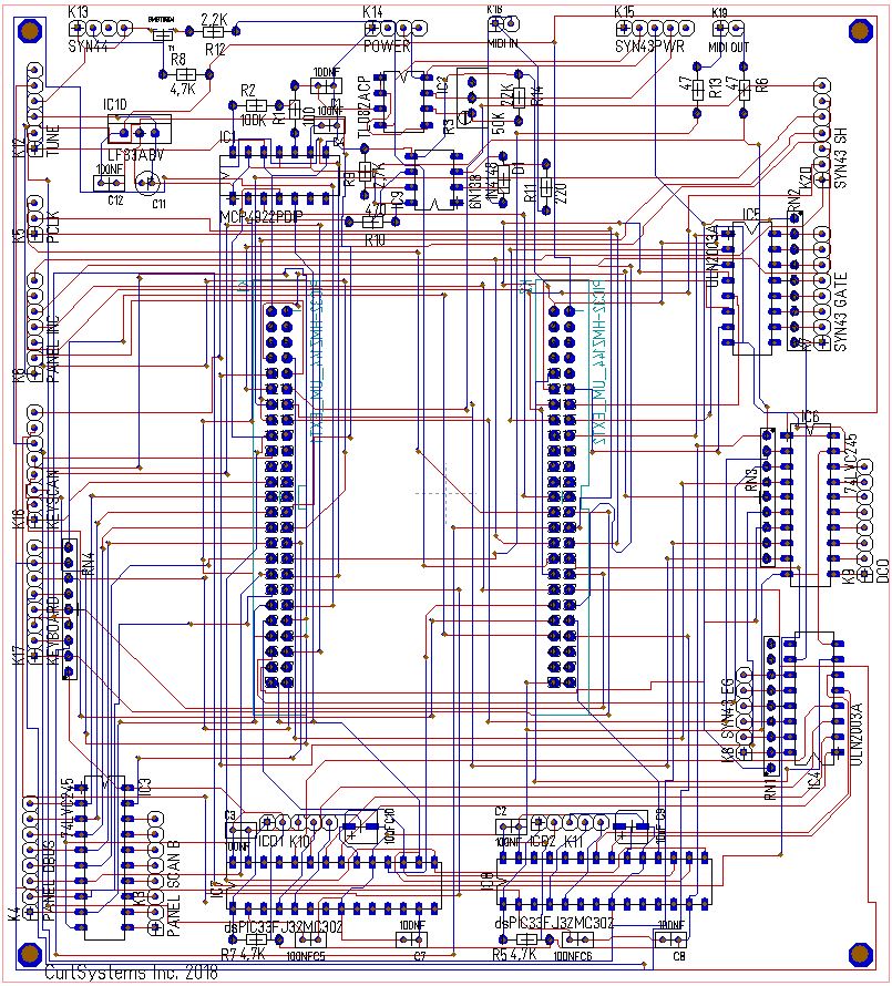
Prototype PCB
I had one powerful Microchip PIC32MZ development board in the drawer which I wanted to use as it was and just plug it on top of my PCB. Furthermore I needed to replace all the obsolete timer ICs which were generating the period triggers for the DCOs and to control the speed of the envelope generators. The PIC32MZ has got 8 PWM outputs which shall do the DCO stuff, and I have furthermore selected two dsPIC33F microcontrollers to control the EGs. Then I have ordered one PCB to start the software development. After one week I had received and assembled it:
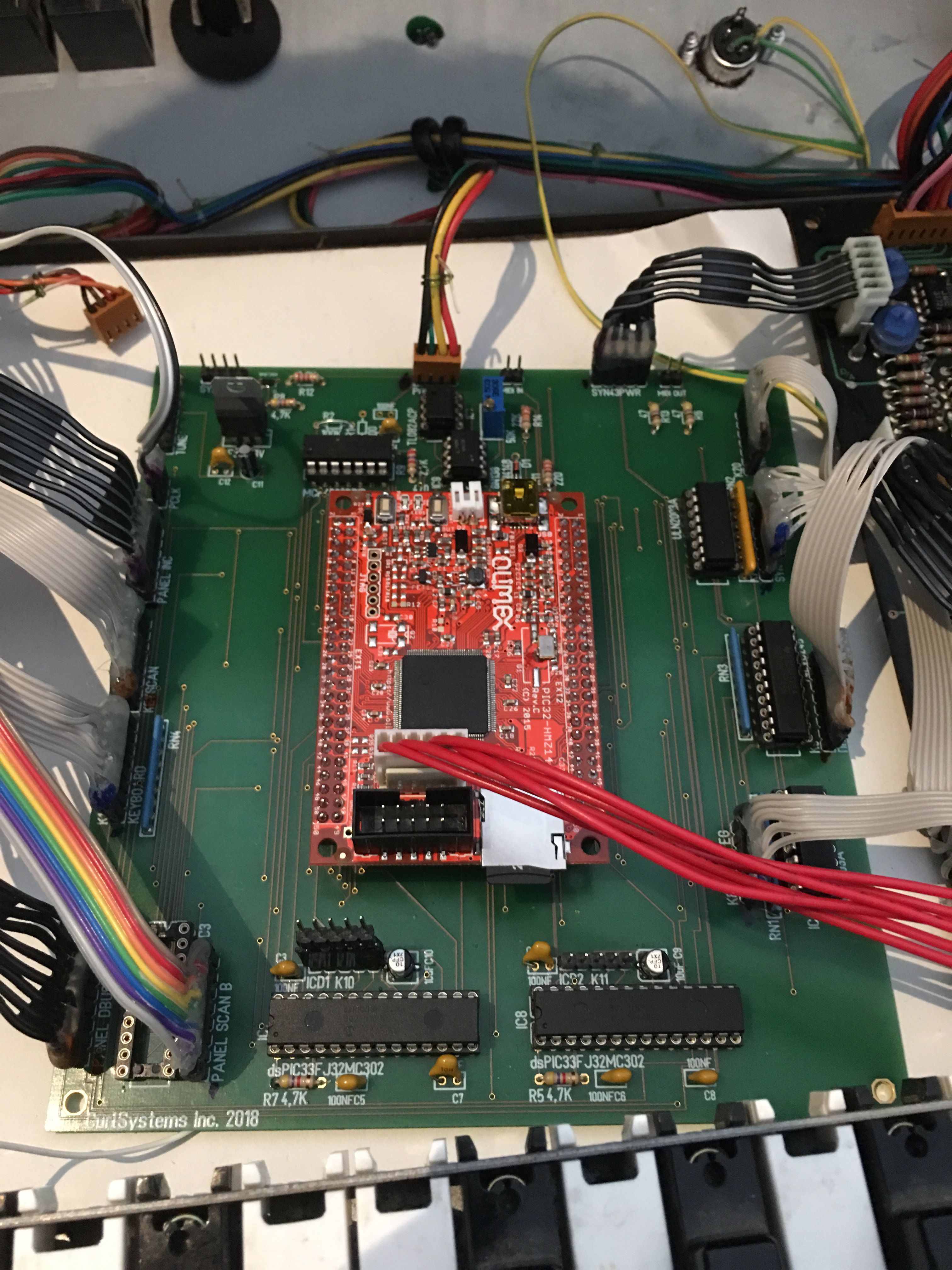
Prototype PCB
Now I could start the first line of codes in order to reimplement all the original features. As the main microcontroller has got now theses specs I could also implement some new features:
PIC32MZ2048EFG144 main MCU:
- 200MHz (old SX210 CPU had just 12MHz)
- 512KB RAM (compared to 2KB before)
- 2MB FLASH
- SD card slot on the development board
First I started to implement all stuff which was required to hear something from the voice board. I figured out the main microcontroller was not the best choice in order to create the period triggers for the DCOs at high frequencies. I could not find any work around in the software so I needed to change the design once more. I found one microcontroller from Microchip which had got individual time bases for each PWM output to create the required signals.
After one week I had implemented all the basic functions and now it was time to start to be able to control all parameters with the front panel. And this was were the nightmare started once more. I was able to control the LEDs and to read in the buttons. But if the rotary encoder has been turned everything was flickering. After checking the service manual I figured out that there was no explanation for this behaviour. I changed code and tried several different control strategies, but with now result. I started to be frustrated. So I checked with a scope every single pin interface to the panel. One week later I figured out what was wrong: It was the original service manual! Argh! One chip select of the latch ICs was not connected as shown in the service manual. I just fixed it and HURRAY! No issues with the front panel anymore.
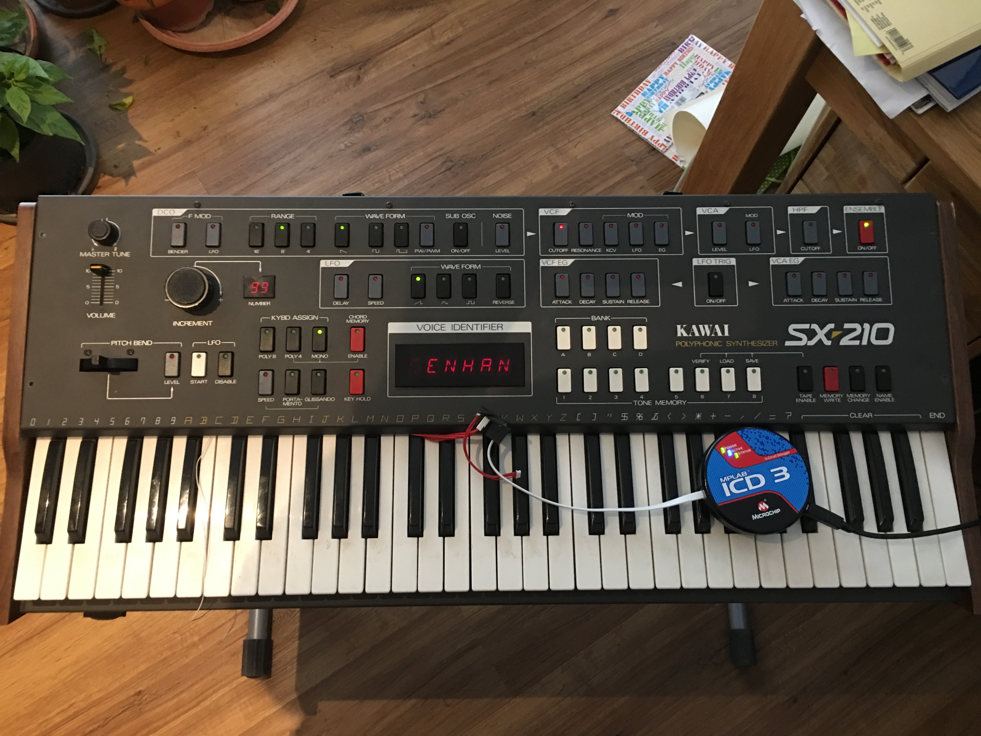
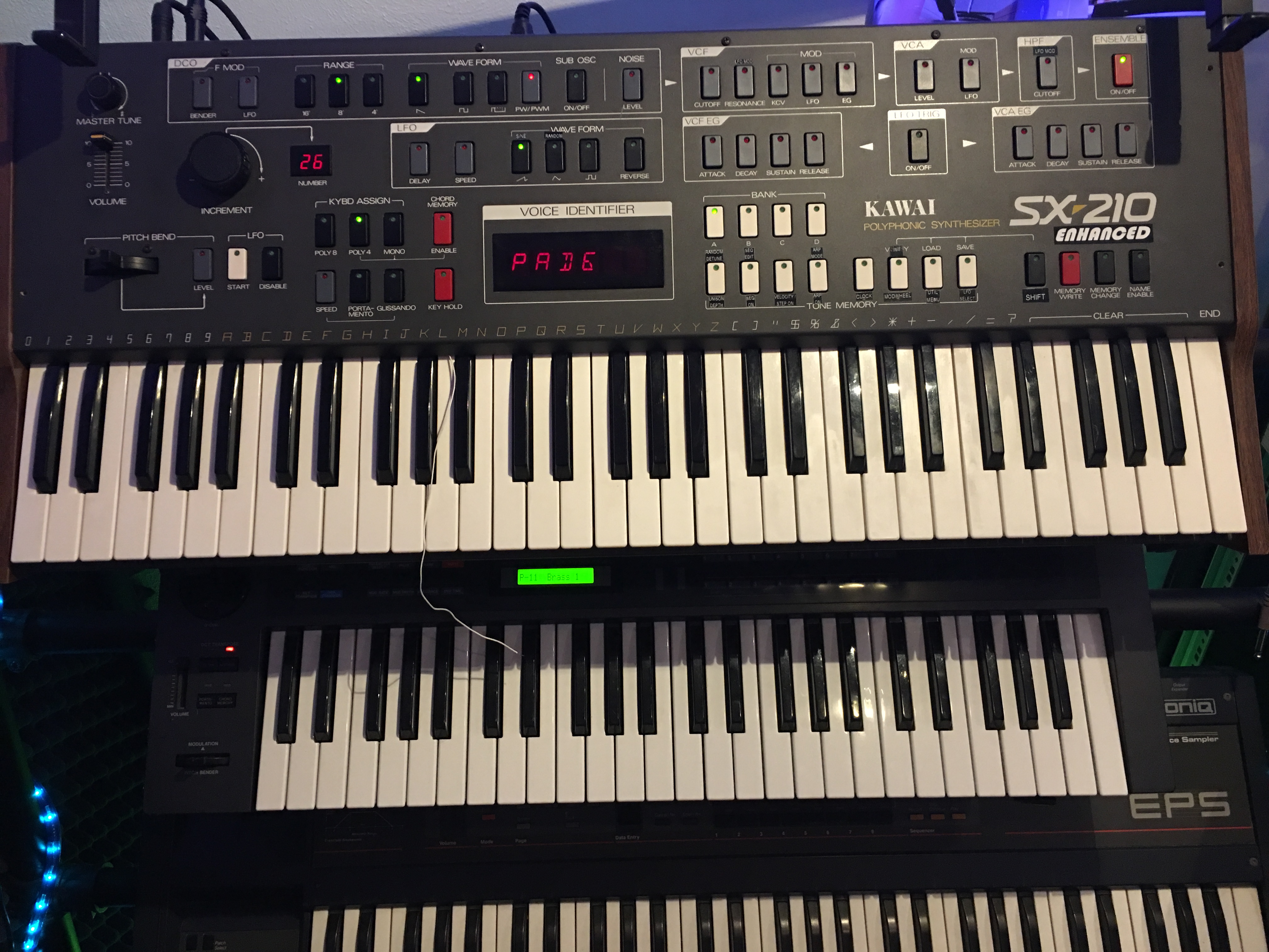
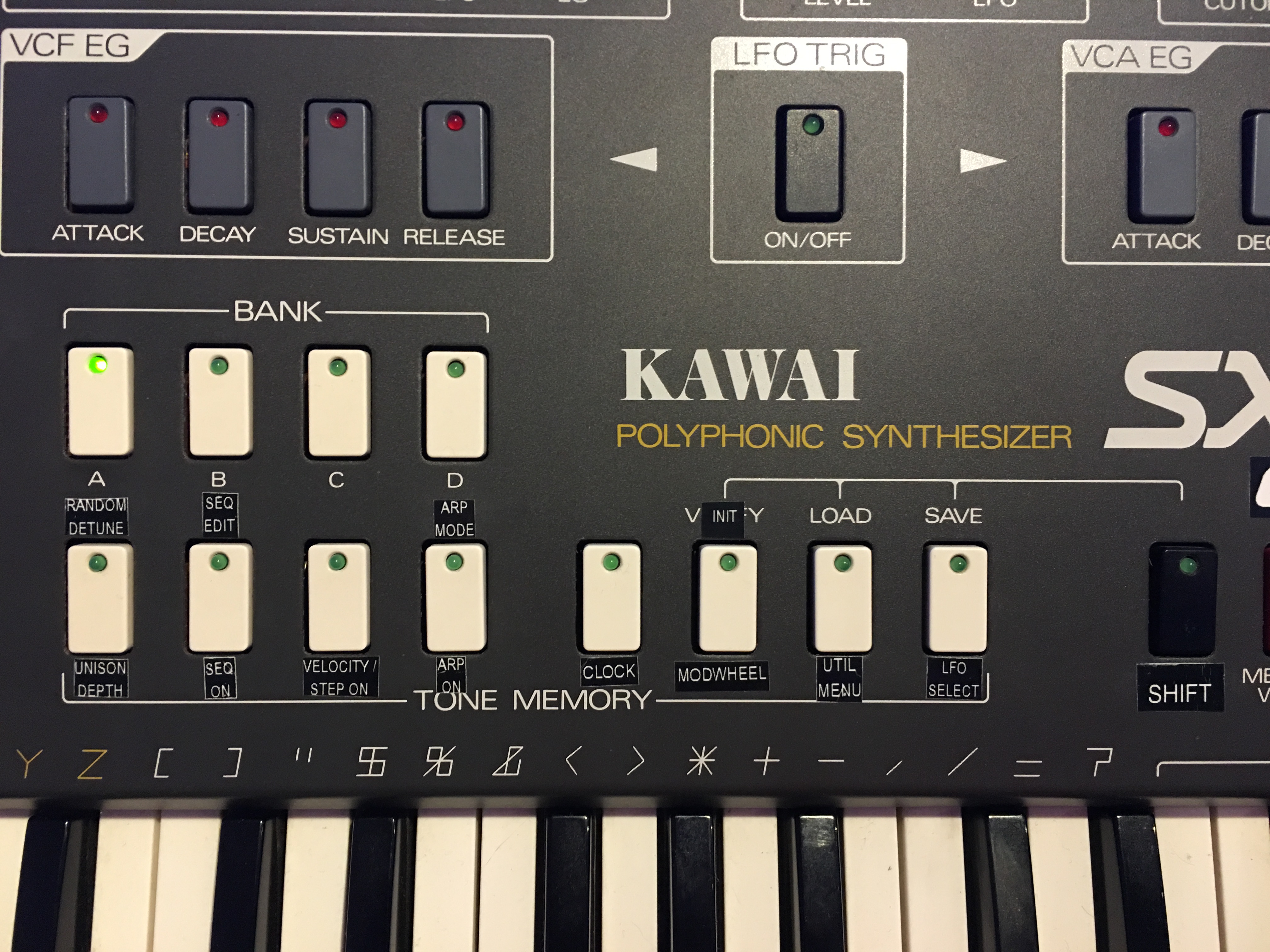
Powered up with new PCB
Now it is time to extend the spec list a little bit with some new features:
- MIDI IN and OUT
- storage of patch data on SD card with FAT filesystem for easy backup with a PC
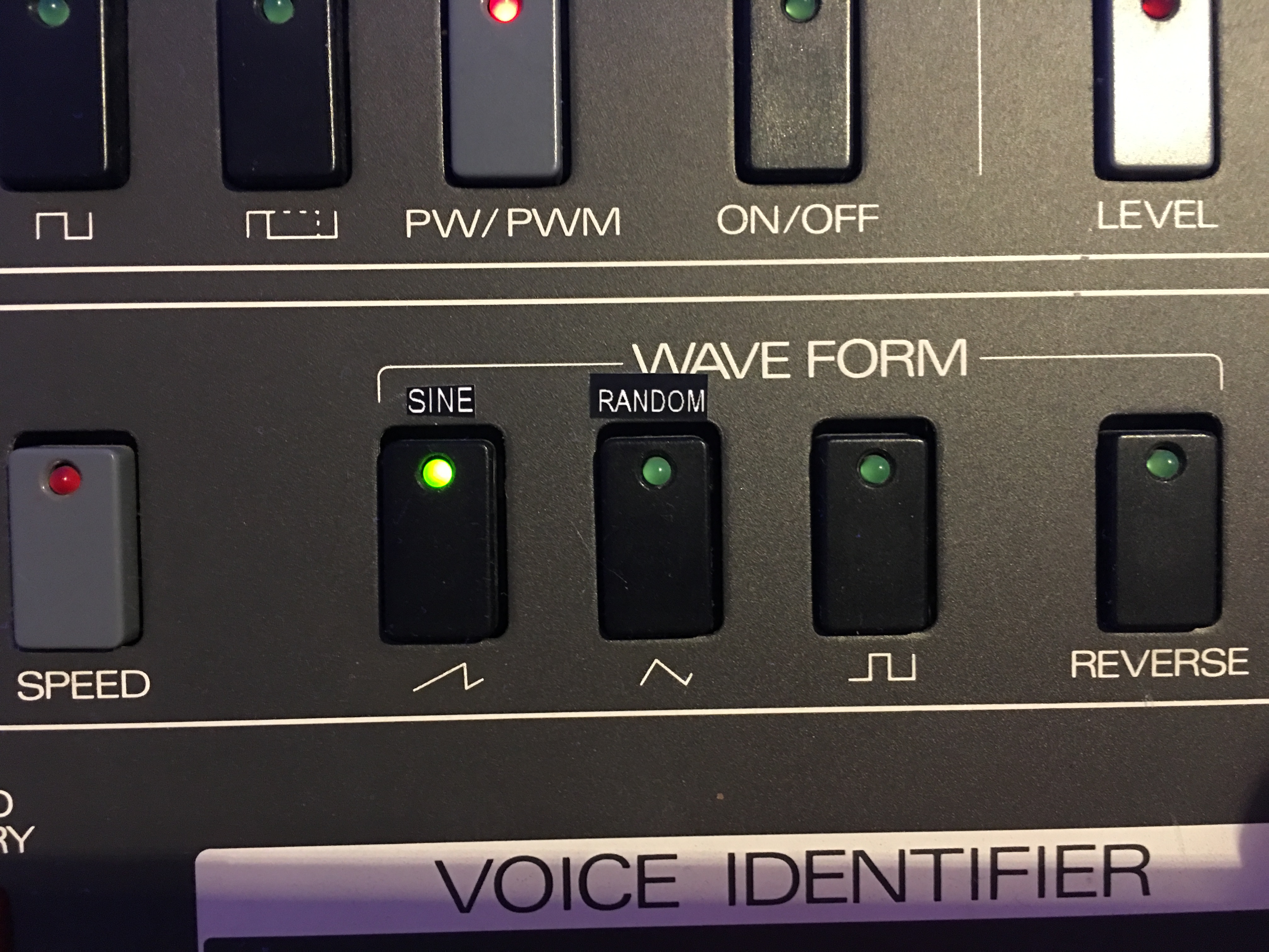
- 4 LFOs (original just 1)
- add sine and random LFO waveforms
- MIDI sync of each LFO
- polyphonic step sequencer supporting velocity per note with up to 99 steps
- arpeggiator (up, down, up/down, random) with 1 to 5 octaves
- MIDI controller support of *all* parameters (RX and TX; by now 95 in total)
- per note control of cutoff by velcoity
- support for longer patch names by using scroll text in the display
- new LFO modulation destinations: HPF and resonance
- pitch bender range up to 99 semitones
- unison detune
- random detune per voice to simulate some detuned old gear
- Modulation wheel targets: cutoff, HPF and LFO gain of each of the 4 LFOs
- 400 memory slots to store own patches
- 12bit DAC for control voltages (10bit before)
By today I managed to realize all of above features.
As I do not have any reference SX-210 with an original computer board I was not able to emulate the original behaviour of LFO speed, portamento, glissandro and EG speeds. So old parameter values are most likely not the same as with the original unit. Furthermore the tape interface for storing patches is not supported anymore.
Currently the upgrade is in prototype state. Unfortunately it looks like it will not become a product as further development (bug fixes, bootloader, CE certification etc.) is required. Costs of a final product with very low quantity would be too high to be accepted.
Sound demo: Kawai SX210 Enhanced Demo1 (master).mp3
All sounds are from the SX210 multitrack recorded and SX210 controlled by MIDI. Some reverb and delay added.
Last update: 28-05-2019